Logic gates with gate symbol and truth table
Every digital computer has digital circuits (IC, LSI) to perform binary operations. These digital circuits are made up of several logic gates and their combination. Thus, logic gates is the basic component of digital computer that operates on one or more input signals to produce an output signal. Each gates has its own specific function, algebraic expression, gate symbol and truth table. In a digital computer AND, OR, NOT are the three fundamental basic gates whereas, NAND, NOR, X-OR, X-NOR are the derived gates from the basic gates. All the logic gates are explained:
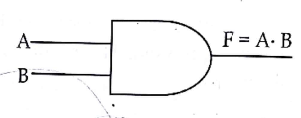
AND gate
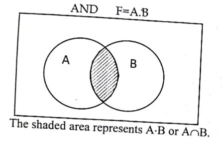
It is an electronic circuit, which produce high logic (1) output when both the input logic are high (1) and produce low logic(0) when any one of the input logic is low (0). The output produce by this basic gate is the product of its input logic.
Algebraic expression
F=A.B where, A and B are inputs, F is an output and “.” Denotes AND operation
Gate symbol;
Truth Table:
| A | B | F=A.B |
| 0 | 0 | 0 |
| 0 | 1 | 0 |
| 1 | 0 | 0 |
| 1 | 1 | 1 |
Venn diagram:
OR gate
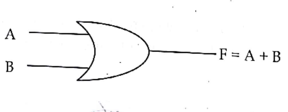
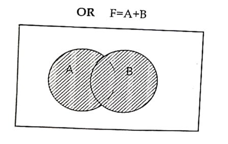
It is an electronic circuit, which produce high logic (1) output when any one of the input logic are high (1) and produce low logic(0) when both the input logic is low (0). The output produce by this basic gate is the sum of its input logic.
Algebraic expression:
F=A+B where, A and B are inputs, F is an output and “+” Denotes OR operation
Gate symbol:
Truth Table:
| A | B | F=A+B |
| 0 | 0 | 0 |
| 0 | 1 | 1 |
| 1 | 0 | 1 |
| 1 | 1 | 1 |
Venn diagram:
NOT gate
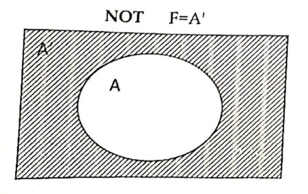
It is an electronic circuit, which produce high logic (1) output when the input logic is low (0) and produce low logic(0) when the input logic is high (1). The output produce by this basic gate is the reciprocal of its input logic.
Algebraic expression:
F=A’ where, A is inputs, F is an output
Gate symbol:
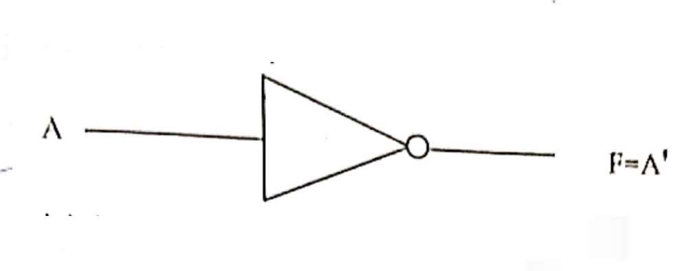
Truth Table:
| A | F=A’ |
| 0 | 1 |
| 1 | 0 |
Venn diagram:
NAND gate
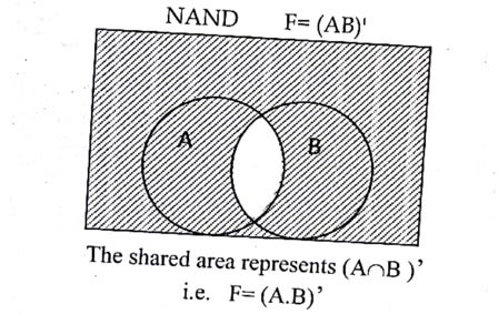
It is the combination of NOT and AND gate, which produce high logic (1) output when any one of the input logic is low (0) and produce low logic(0) when both the input logic is high (1). The output produce by this basic gate is the reciprocal or complement of AND gate. It is also known as derived gate.
Algebraic expression:
F=(A.B)’ where, A and B are inputs, F is an output.
Gate symbol:
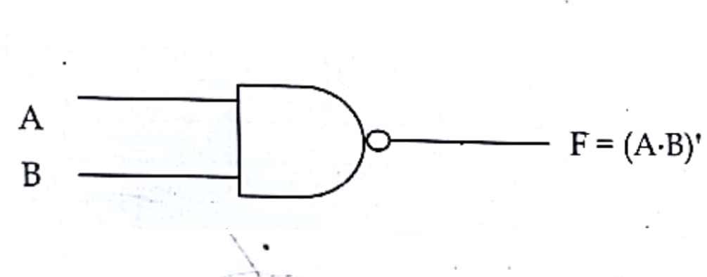
Truth Table:
| A | B | A.B | F=(A.B)’ |
| 0 | 0 | 0 | 1 |
| 0 | 1 | 0 | 1 |
| 1 | 0 | 0 | 1 |
| 1 | 1 | 1 | 0 |
Venn diagram:
NOR gate
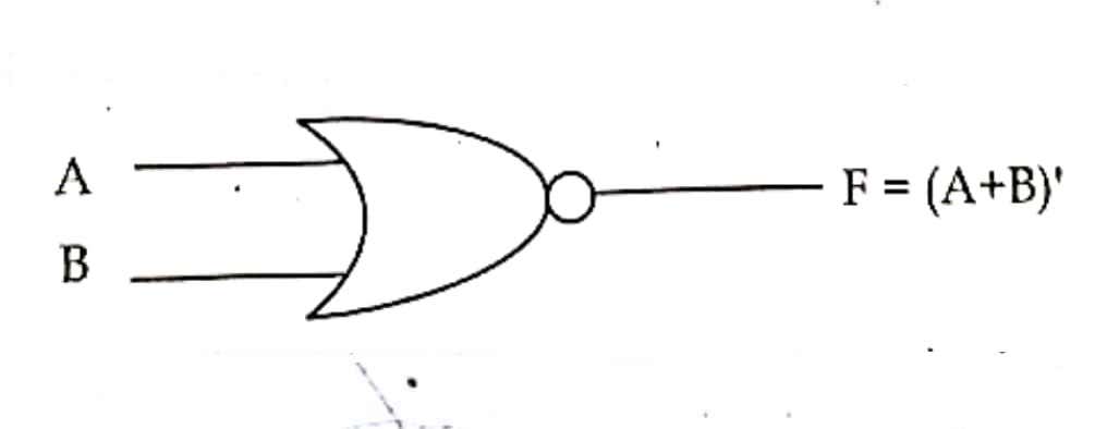
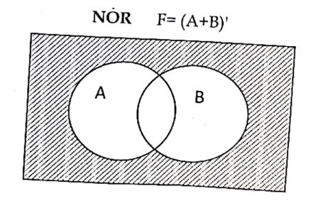
It is the combination of NOT and OR gate, which produce high logic (1) output when both the input logic is low (0) and produce low logic(0) when any one of the input logic is high (1). The output produce by this basic gate is the reciprocal or complement of OR gate. It is also known as derived gate.
Algebraic expression:
F=(A+B)’ where, A and B are inputs, F is an output.
Gate symbol:
Truth Table:
| A | B | F=A+B | F=(A+B)’ |
| 0 | 0 | 0 | 1 |
| 0 | 1 | 1 | 0 |
| 1 | 0 | 1 | 0 |
| 1 | 1 | 1 | 0 |
Venn diagram:
X-OR gate
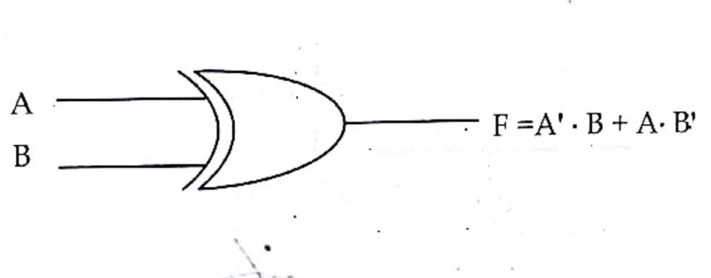
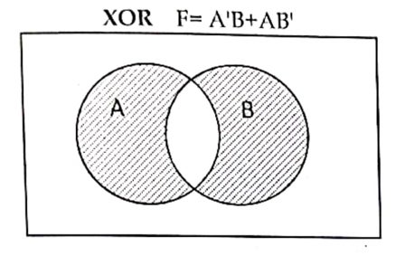
It is derived gate, which produce low logic (0) output when both the input logic are either high (1) or low (0) otherwise it will produce high logic(1).
Algebraic expression:
F=A’.B+A.B’ where, A and B are inputs, F is an output.
Gate symbol:
Truth table:
| A | B | A’ | B’ | A’.B | A.B’ | A’.B+A.B’ |
| 0 | 0 | 1 | 1 | 0 | 0 | 0 |
| 0 | 1 | 1 | 0 | 1 | 0 | 1 |
| 1 | 0 | 0 | 1 | 0 | 1 | 1 |
| 1 | 1 | 0 | 0 | 0 | 0 | 0 |
Venn diagram:
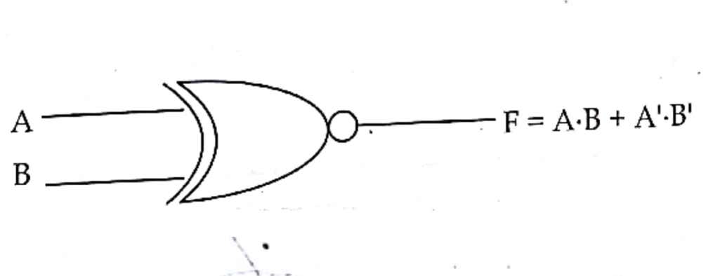
X-NOR gate
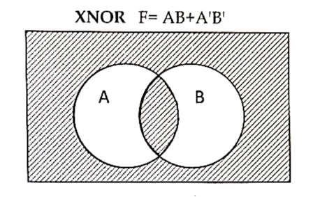
It is derived gate, which produce high logic (1) output when both the input logic are either high (1) or low (0) otherwise it will produce low logic(0).
Algebraic expression:
F=A.B+A’.B’ where, A and B are inputs, F is an output.
Gate symbol:
Truth table:
| A | B | A’ | B’ | A.B | A’.B’ | A’.B+A.B’ |
| 0 | 0 | 1 | 1 | 0 | 1 | 1 |
| 0 | 1 | 1 | 0 | 0 | 0 | 0 |
| 1 | 0 | 0 | 1 | 0 | 0 | 0 |
| 1 | 1 | 0 | 0 | 1 | 0 | 1 |
Venn diagram:
Click here for e-notes
